Repairing Switching Mode Power Supplies audioXpress
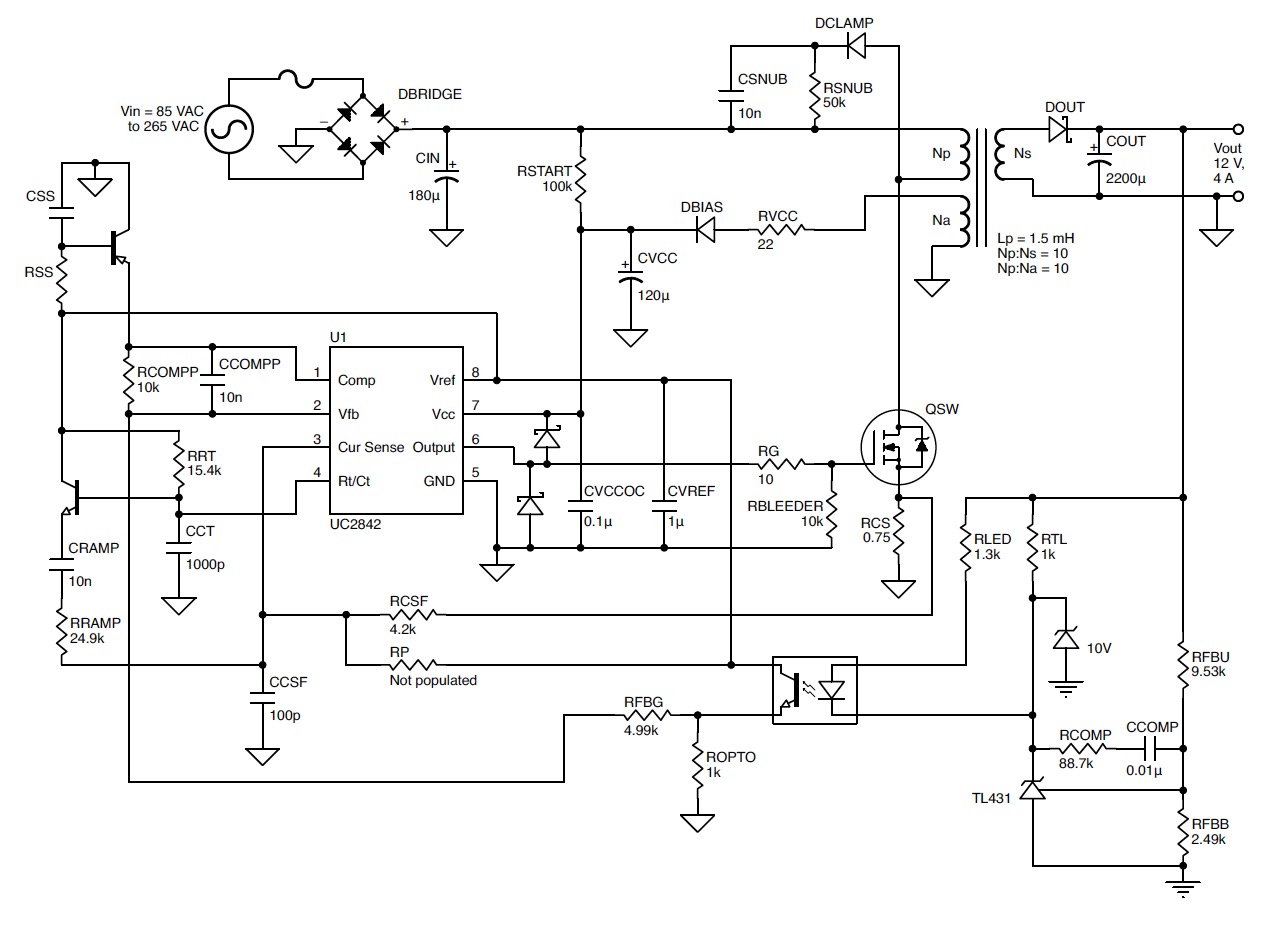
AC/DC Switch Mode Power Supply Design Guide Fairchild Power Switch (FPS) Green FPS Part Application PO(max) (W) PO(max) (W) Peak Current HV-FET Rating R DS(ON) max (Ω) Switching Frequency Package Number 85-265VAC 230VAC ±15% Limit (A) (V) Frequency (V) Mod. (kHz) FSCM0565RC STB, LCD Monitor 70 85 2.5 650 2.2 66 Yes TO220-5L
Switching Power Supply Schematic MAXIPX
This manual includes basic information for switching power supply, general specifications, safety regulations, EMC standards, CE, reliability, operation notes, technical Q&A, and notes on failure correction.
Ac Dc Switching Power Supply Schematic
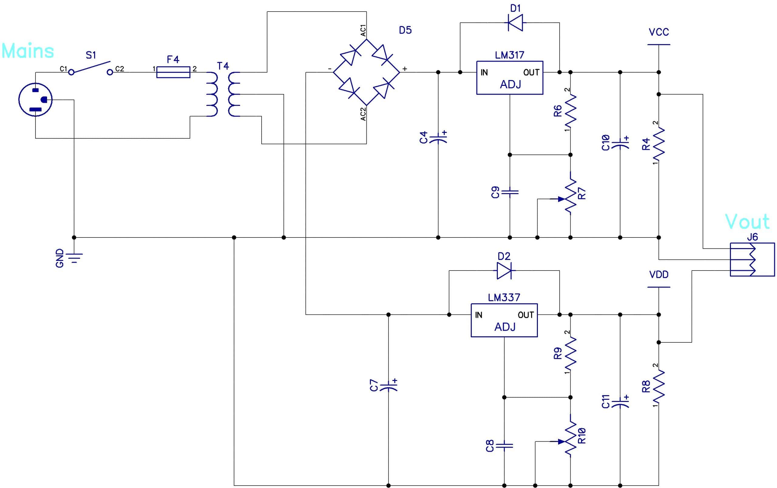
There are two main reasons, and both relate to cost. First, linear power supplies require large and expensive transformers. Second, the regulating transistor generates a lot of heat, which requires large and expensive heat sinks. For example, a 50V variable power supply set to output 5V at 2A might have (50V - 5V) * 2A = 90W of heat to dissipate.
11+ Switching Power Supply Schematic Robhosking Diagram
The most commonly used DC/DC converter circuits will now be presented along with the basic principles of operation. 2.1 Buck Regulator The most commonly used switching converter is the Buck, which is used to down-convert a DC voltage to a lower DC voltage of the same polarity. This is essential in systems that use distributed power rails (like
Atx Power Supply Circuit Diagram Pdf Wiring Diagram
Whether you are an experienced power supply designer, designing your first switching power supply or responsible for a make or buy decision for power supplies, the variety of information in the Switch−Mode Power Supply Reference Manual should prove useful.
Ac Dc Switching Power Supply Schematic
Introduction to Switched Mode Power Supplies. SMPS circuits are considerably more complex than the linear stabilised power supplies described in Power Supplies Module 2. The main advantage of this added complexity is that switched mode operation gives stabilised designs that can deliver more power for a given size, cost and weight of power unit.
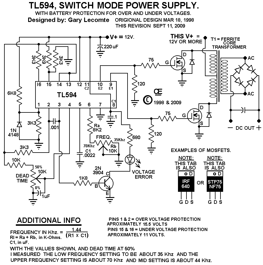
12 Volt Switching Power Supply Schematic
Light weight . The ALS-600SPS is a light weight switching power supply to use with the ALS-600 amplifier. It is 1/3 rd the weight of the ALS-600PS linear power supply. The ALS-600 amplifier with the ALS-600SPS switching power supply is ideal for travel. Hash free . The specially designed switching and filter circuit makes the power supply hash.
Build a Switching Power Supply Circuit Diagram Electronic Circuit
Switch-mode power supplies (SMPSs) are frequently used to provide the various levels of DC output power needed for modern applications, and are indispensable in achieving highly efficient, reliable DC-DC power-conversion systems. Why SMPS? The majority of electronic DC loads are supplied from standard power sources.
Design Kit Quasiresonant Switching Power Supply Modeling and
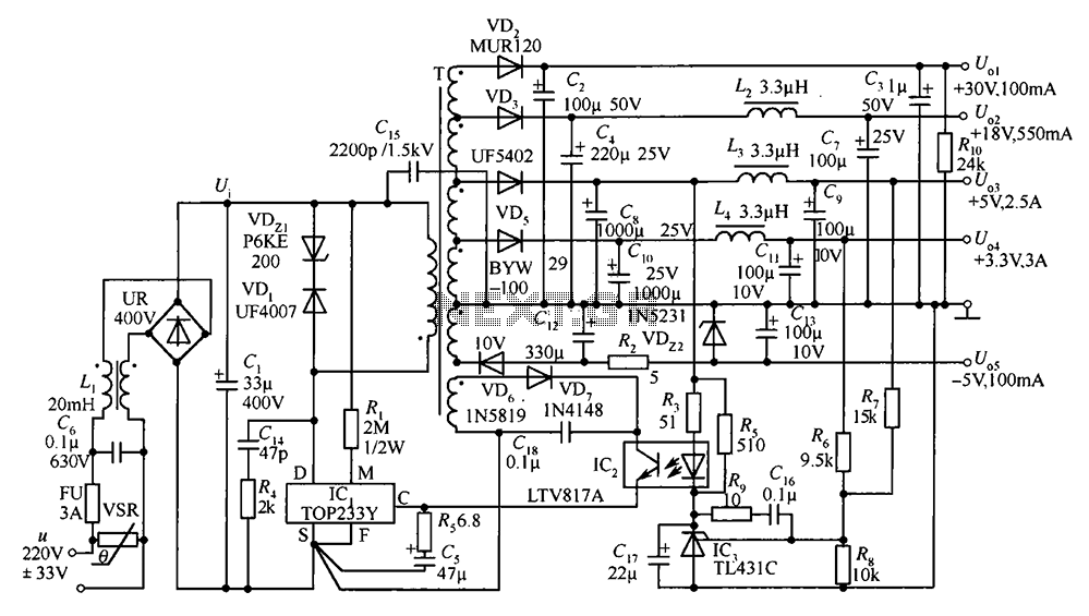
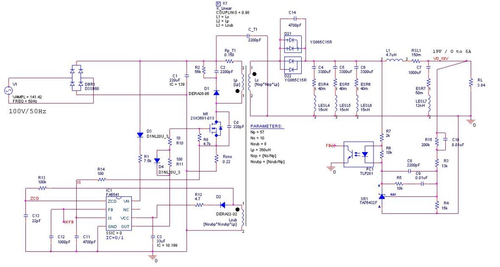
The main circuit of the switching power supply is composed of an input electromagnetic interference filter (EMI), a rectification and filtering circuit, a power conversion circuit, a PWM controller circuit, and an output rectification and filtering circuit. The auxiliary circuit has an input over-voltage protection circuit, an output over.

Switching power supply
The Basic Device. The design of the TL494 not only incorporates the primary building blocks required to control a switching power supply, but also addresses many basic problems and reduces the amount of additional circuitry required in the total design. Figure 1 is a block diagram of the TL494.

Switching Power Supply Schematic MAXIPX
There are three types of switching power supplies: Step down regulator - sometimes called a "buck" regulator. Step up regulator - sometimes called a "boost" regulator. Inverting regulator - sometimes called a "flyback" regulator. In Project #2 we will focus on buck and boost regulator design.

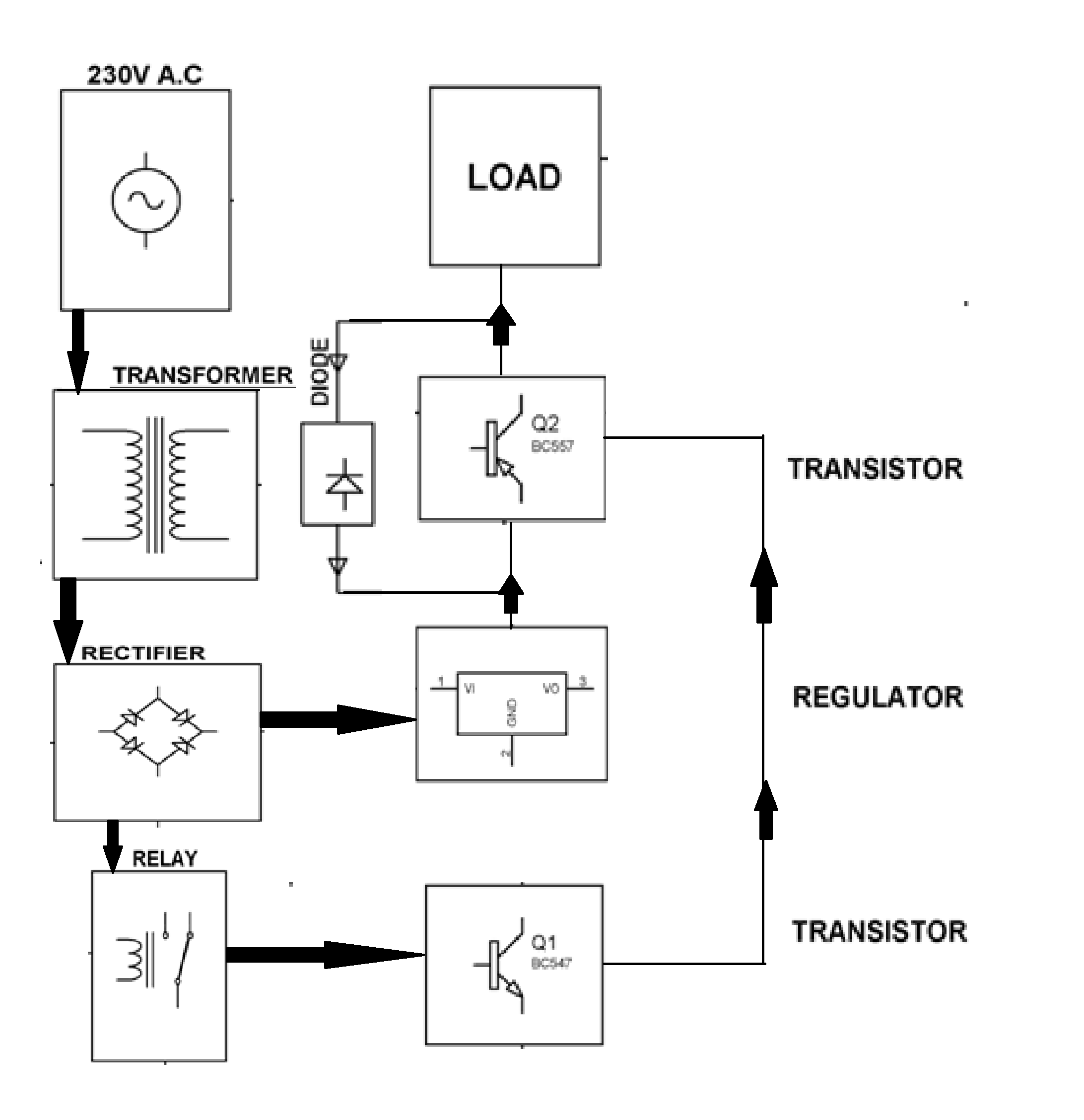
Self Switching Power Supply Circuit Diagram
TL494, NCV494. The TL494 is a fixed frequency, pulse width modulation control circuit designed primarily for switch mode power supply control. MAXIMUM RATINGS (Full operating ambient temperature range applies, unless otherwise noted.) Stresses exceeding those listed in the Maximum Ratings table may damage the device.

± 60 Volt Switching Power Supply for PA Power Supply Circuits
The semiconductor switches used to implement switch mode power supplies are cont inuously switched on and off at high frequencies (50 kHz to several MHz), to transfer electrical energy from the input to the output through the passive components.
11+ Switching Power Supply Schematic Robhosking Diagram
By definition, a switch mode power supply (SMPS) is a type of power supply that uses semiconductor switching techniques, rather than standard linear methods to provide the required output voltage. The basic switching converter consists of a power switching stage and a control circuit.

12v Power Supply Circuit Diagram Pdf
Figure 1: The step down "Buck" regulator The power device is switched at a frequency f = 1/T with a conduction duty cycle, δ = t on /T. The output voltage can also be expressed as: V out = V in . δ Device selection: * Power switch: V cev or V DSS > V in max * Rectifier: V RRM ≥V in max I F(AV) ≥ I out (1-δ) ∆I I cmax or I D max > I out + 2 ∆
How to Build a Switch Mode Power Supply Circuit Basics
Power supply unit (PSU) usually works to convert utility AC voltage into regulated DC voltages to be used by the equipment. In most PSU, the energy flow is controlled with semiconductors which are continuously switching on and off with high frequency. Such kind of PSU are referred to as switch mode power supplies or SMPS .